

Chapter 5
I 1788 - State Of The Art In Textile Technology
II Australian Textiles - The Early Days
III Australian Textiles - The 20th Century
i Technology and Development
ii Australian Wool Textile Research
IV Australian Textiles - To Date
V Acknowledgements
References
Index
Search
Help
Contact us
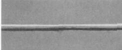
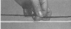
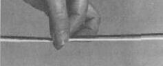
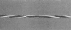
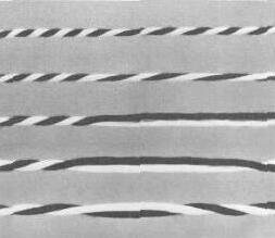
Between adjacent S and Z two-ply twists is a zone containing no twist. This is shown in the fourth photograph, which is a weak point in the structure. Therefore, a yarn in this form is unsuitable for weaving. The necessary strength is given to the yarn by a subsequent twisting operation. The final photograph shows in five discrete steps the effect of adding unidirectional twist to a self-twist structure. When additional twist is applied, the twist in the right-hand portion of the yarn (a) increases as the yarn to the left of the no-twist zone starts to untwist (b). Further twisting removes all twists from the left half of the yarn (c), without the loss of roving twist. Addition of more twist results in the condition shown in (d), where all the twist is unidirectional, and finally in that shown in (e), where twist distribution approaches uniformity. The yarn in this form has the necessary characteristics for fabric weaving.
In the early stages of the development of self-twist, many methods of making alternating-twist structures were considered. The conflicting requirements of high-twist insertion accompanied by low strand tension to avoid strand breakage limited the choice of methods. A reciprocating roller system fulfilled these requirements, with the added prospect of very high production rates.
Using the reciprocating roller system, two separated parallel rovings are first conventionally drafted and then enter the nip of a pair of rollers, which not only rotate, but simultaneously reciprocate through equal distances in opposite directions.
The frictional contact between the rotating rollers and the strands carries the latter forward, and the traverse motion of the rollers rolls the strands, causing them to twist. By this means alternate zones of S and Z twist are imparted progressively to the separate strands as they pass through the rollers. Finally, the two twisted strands are combined and twist about one another to form a stable two-ply structure.
 |
Australian Academy of Technological Sciences and Engineering |  |
© 1988 Print Edition pages 282 - 284, Online Edition 2000
Published by Australian Science and Technology Heritage Centre, using the Web Academic Resource Publisher
http://www.austehc.unimelb.edu.au/tia/290_image.html